Ротаметры Swagelok®
Ротаметры Swagelok обеспечивают последовательную точность результатов измерения расхода газов и жидкостей. В зависимости от ваших условий и требований мы поставляем варианты со стеклянными или металлическими трубками.
Запросить дополнительную информациюВ ротаметрах Swagelok® используется коническая трубка и поплавок для измерения расхода жидких и газовых сред. При увеличении расхода поплавок поднимается, а при уменьшении сила тяжести тянет его вниз. Такие устройства легко монтируются, считываются и не имеют изнашивающихся частей, что сводит к минимуму необходимость в техническом обслуживании. Динамический диапазон измерений 10:1—обеспечивает необходимую точность при наименьшем измерении, равному 1/10—от максимального показания. Они выпускаются с американской и метрической шкалой, что позволяет использовать их в самых разных уголках мира.
Каждый ротаметр Swagelok откалиброван в заводских условиях с учетом технологической среды, диапазона расхода и класса точности с использованием чистого, сухого воздуха для газовых моделей, и воды для жидкостных моделей. Также могут быть откалиброваны под конкретные задачи пользователя.
Ротаметры серии M (модели M1, M2, M4 и M4H)
Расходомеры Swagelok® серии M оснащены металлическими измерительными трубками для работы в сложных условиях высокой температуры или давления. Поскольку с металлическими трубками прямые показания невозможны, в таких моделях предусмотрены механическими или электронными дисплеи для обеспечения четкого и точного контроля.
Технические характеристики моделей M1, M2, M4, и M4H
| Измеряемые диапазоны расхода | Воздух: От 0,18–1,8 до 670–6700 ст. фут³/ч; от 5,0–50 до 18000–180000 ст. л/ч Вода: От 0,08–0,8 до 270–2700 гал/ч; от 0,3–3,0 до 1000–10000 л/ч |
| Диапазоны температур | Техпроцесс: M1, M2: От –40 до 302°F (от –40 до 150°С) M4, M4H: От –40 до 572°F (от –40 до 300°C) Окр. среда: M1, M2: От –4 до 158°F (от –20 до 70°C) M4, M4H: От –40 до 248°F (от –40 до 120°С) |
| Максимальное давление на входе | До 2888 psig (199 бар ман) |
| Соединения с технологическим оборудованием | Фитинг с резьбой NPT от 1/4 до 1 1/4 дюйма; фланцевый переходник ASME от 1/2 до 1 дюйма |
| Класс точности | 1,6; 2,5; 4,0 |
Ротаметры серии G (модели G1, G2, G3, G4, GM и GP)
В моделях Swagelok® серии G используются стеклянные измерительные трубки для обеспечения видимости технологической среды и непосредственного снятия показаний расхода.
Технические характеристики моделей G1, G2, G3, G4, GM и GP
| Измеряемые диапазоны расхода | Воздух: От 0,018–0,18 до 18–180 ст. фут³/ч; от 0,5–5,0 до 500–5000 ст. л/ч Вода: От 0,065 до 0,65–от 4,2 до 42 галлонов США/ч; от 0,04 до 0,4–от 16 до 160 л/ч |
| Диапазоны температур | Техпроцесс: от 23 до 212°F (от –5 до 100°C) Окружающая среда: от –4 до 212°F (от –20 до 100°C) |
| Максимальное давление на входе | До 145 psig (10 бар ман) |
| Соединения с технологическим оборудованием | Фитинг с резьбой NPT 1/4 дюйма; G 1/8 (ISO 228); G 1/4 (ISO 228) |
| Класс точности | 1,0; 2,5; 4,0 |
Нужна помощь с выбором расходомера?
Каталоги ротаметров
Получите подробные сведения о продукции, в том числе материалах изготовления, номинальных параметрах давления и температуры, вариантах исполнения и вспомогательных принадлежностях.
Features: Glass and metal (armored) tube models, including miniature armored model; Highly accurate measurement even at very low flow, with individually calibrated scales based on flow tests; Flexible and adaptable to specific system requirements; High quality, durability, and repeatability; 1/8 to 1 1/4 in. process end connections

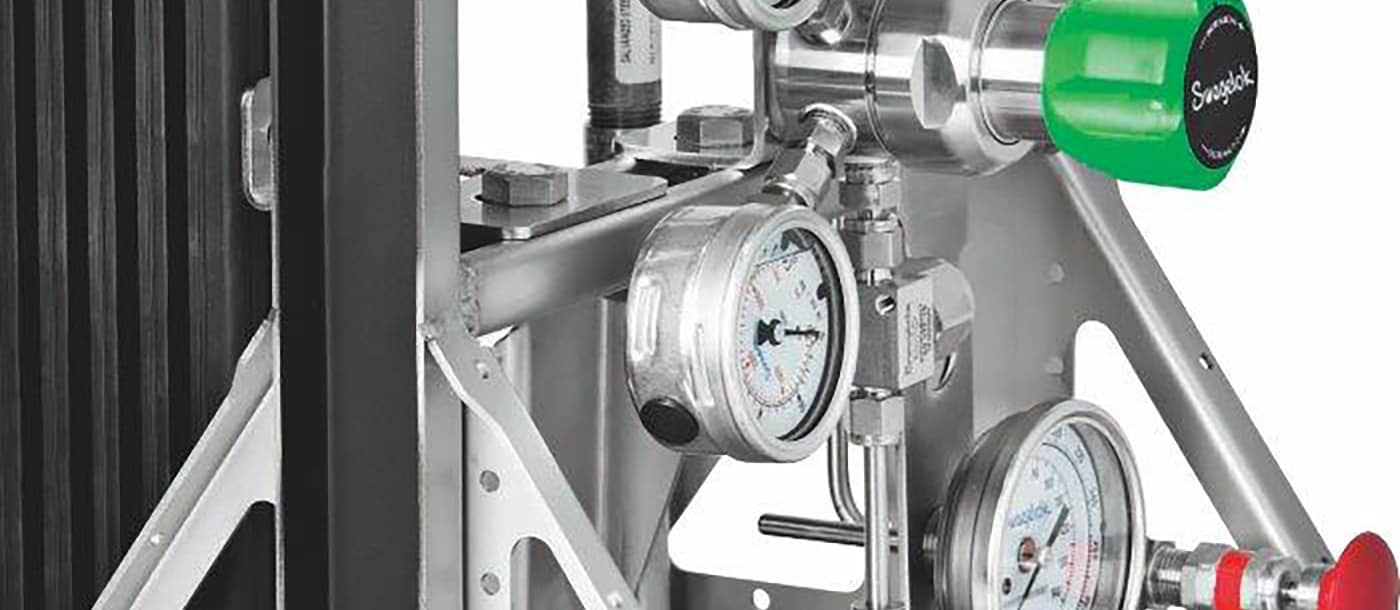
Небольшой, но важный прибор: Как выявить и предупредить неисправность манометра
Узнайте, как распознать признаки неисправности манометра и тем самым избежать опасности для сотрудников и дорогостоящего простоя оборудования из-за вынужденного ремонта.
Узнайте, как предупредить неисправность манометраРесурсы Swagelok специально для вас

Рекомендации по обеспечению репрезентативности проб в аналитической контрольно-измерительной системе
Обеспечение репрезентативности проб в аналитической контрольно-измерительной системе может стать сложной задачей. Узнайте у специалистов компании Swagelok, как выявить основные проблемы и избежать сложностей, вызванных нерепрезентативными пробами.

Обзор решений с использованием вспомогательных систем торцевых уплотнений
Узнайте, как во вспомогательных системах торцевых уплотнений Swagelok® для стандарта API 682 применяется передовой опыт API 682, а также принципы проектирования, которые делают системы удобными в монтаже и техобслуживании.

Как жидкостные и газовые системы могут сгладить ограничения, вызванные нехваткой ресурсов
Есть несколько распространенных жидкостных и газовых систем, от которых зависит успешная работа производства, поэтому, если у вас мало ресурсов, выбор подходящего подрядчика может принести много пользы.

Технологические измерения—передовой опыт для импульсных линий
Если сосредоточить внимание только на датчике, найти проблемы в КИП может быть сложно. Советы и передовой опыт компании Swagelok помогут вам научиться решать проблемы на вашей технологической линии КИП.
